Installation
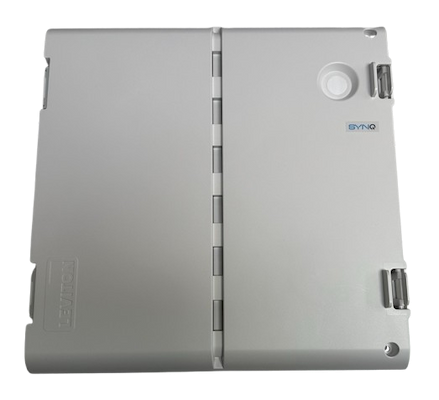
Exterior Front View
Interior Front View
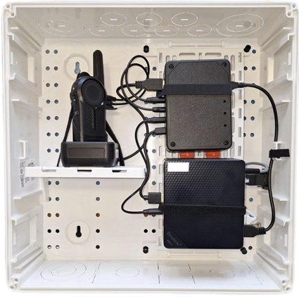
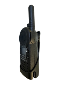
This kit features a Motorola DLR1020.
Exterior Right Side View
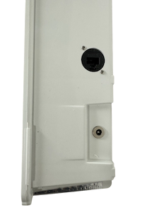
Jacks:
- Top: Ethernet
- Bottom: Power
Pre-Installation Checklist
Donor Radios
- Confirm the location uses a SYNQ supported radio model.
- You will need two radios to complete the installation.
- Radio #1 is the "donor" radio that remains permanently docked/connected inside the radio kit.
- Radio #2 is for testing the system and can be returned when installation completes.
- Verify that the radios are on the channel, frequency, and privacy code used at this location.
- Verify that the radios are able to communicate with each other.
- Turn both radios on.
- Press the push-to-talk button on Radio #1 and say a test phrase like "testing-testing 1-2-3". You should be able to hear the message on Radio #2.
- Repeat from Radio #2 to confirm it can communicate with Radio #1.
- Disable the "Roger Beep" feature on the Radio #1 (if applicable).
The donor radio needs to be in good working condition.
Location
It is important to select a suitable install location for the radio kit.
- Test that radios operate normally with good reception and transmission from this location.
- Does the location have Ethernet accessible?
- Does the location have 110V power?
- Does the location have a wall to mount the radio kit to, or a shelf that it can sit on?
- Is the location secure so that the kit will not be tampered with?
The install location needs to be in an area with good radio reception. Do not sacrifice radio reception quality, for ease of installation.
Network
When the device is plugged into Ethernet will it be able to reach the internet? Or are there special networking requirements that must be satisfied?
- Does the device need to be pre-assigned to a specific VLAN?
- We can provide the MAC Address and host name of the device.
- If your network uses a security appliance that requires devices to use a specific Root CA certificate, contact us to ensure the device is pre-provisioned with the necessary certificates.
Tools and Supplies Needed
- Pencil
- Bubble level
- Screwdriver
- Screws
- Wall anchors
- Ethernet patch cable
Wall Mounting
The case is equipped with four keyhole anchor points for wall/surface mount applications.
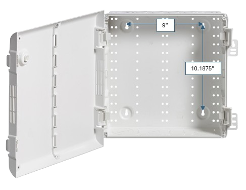
The kit includes a paper mounting template that you can use to mark the locations for the anchor screws.
The mounting hardware (screws and wall anchors) are not included.
Installation Procedure
- Open the radio kit by squeezing the two tabs on the right.
- Remove the power adapter plug from the kit.
- Remove the paper wall mounting template from the kit.
- Mounting the kit.
- Position the paper wall mounting template on the desired wall location.
- Ensure the template is level.
- Mark the four hole locations.
- Install screws/wall anchors.
- Hang the kit on the wall anchors using the four keyhole anchor points.
- Turn on Radio #1 (the one to be mounted inside the kit) to ~50%.
- Verify that the radio is on the channel, frequency, and privacy code used at the location.
- Connect the donor radio speaker/mic jack(s) to the hardware adapter. This step can vary depending on your radio model.
- For most radio this means connecting the 3.5mm (speaker) and 2.5mm (microphone) audio cables from the hardware adapter to the corresponding speaker and microphone jacks on the radio.
noteYou may need to open an accessory cover to access the speaker/mic jack(s).
- For most radio this means connecting the 3.5mm (speaker) and 2.5mm (microphone) audio cables from the hardware adapter to the corresponding speaker and microphone jacks on the radio.
- Place the radio in the charging the dock inside the kit.
- Ensure it is properly seated in the dock and clipped in.
- Use the supplied Velcro strap to secure the radio.
- Connect Ethernet
- Connect Ethernet to the jack on the lower right-hand side on the outside of the kit.
- Connect other end of Ethernet cable to your network switch.
- Turn on Radio #2.
- Connect Power
- Connect the power adapter to the lower right-hand side on the outside of the kit.
- Plug the power adapter into a 110V power outlet.
- The radio kit will start up automatically.
- Verify that the blue LED power indicator illuminates on the PC within the case.
- Verify that the red LED power indicator illuminates on radio adapter.
- Wait one minute.
- Depending on your settings you may hear a "SYNQ Radio (Channel #) is online." announcement after approximately 10 seconds.
- Sign into MyStore as a Location Administrator.
- Select Radio.
- The Transcript Viewer opens to the first channel and current date.
- Select the desired channel if you have multiple radio kits.
- Speak a test phrase into Radio #2. For example, "testing-testing 1-2-3".
- You should see the transcription of your test phrase appear.
- Type in a test phrase into chat interface of the transcript viewer and press the Send button.
- The test phrase will be broadcast over the radios.
- You should hear it through Radio #2.
- If applicable, verify that the LED indicator on the charging dock is illuminated. Different charging docks provide different indicators, but typically:
- Solid red means charging.
- Solid green means fully charged.
- Flashing red means an error state.
- Verify that the Radio #1 is firmly seated the charging the dock inside the kit.
- Close the case.
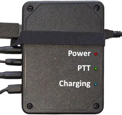
Radio Adapter LEDs
The Radio Adapter provides three indicator LEDs.
- Red: Power
- Green: Push-to-talk (PTT) enabled
- Blue: Charging enabled